2.2 Project
Project file carries various setting information.
Let's see an example.
- Menu => Verilog Project
- Menu => Load Project
Select "vcd_test.vtakprj" in "samples" folder.
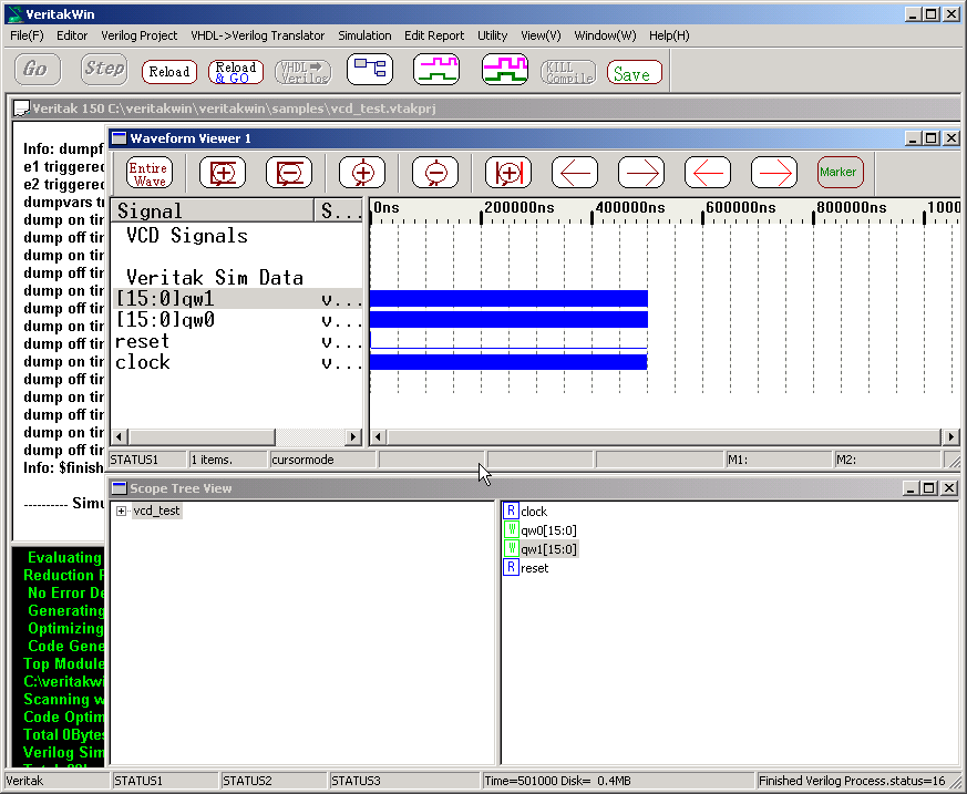
After Compilation, press
Go button. You should see following display.
Since WaveformView information was saved in vcd_test.vtakprj, we can see
signals with just pressing Go button.
2.4.1 VCD
2.4.1.1 Single File
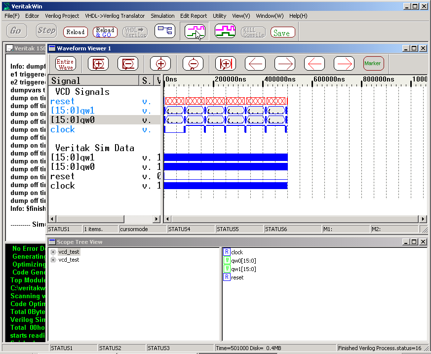
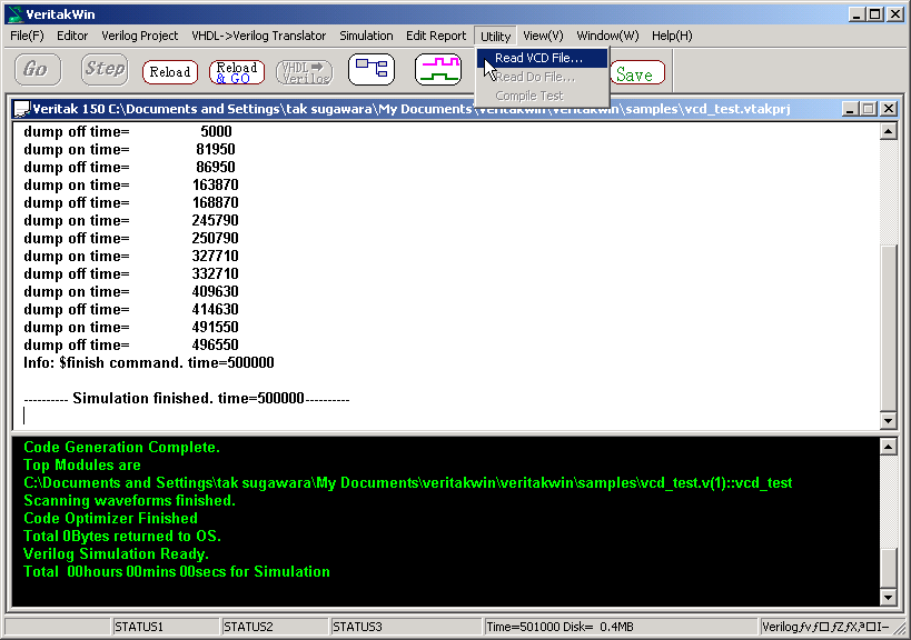
In this project, VCD signals was also saved. To read VCD data ,all views
must be dismissed.
- Menu Utility=> Read VCD Files...
Open "vcd_test.vcd".
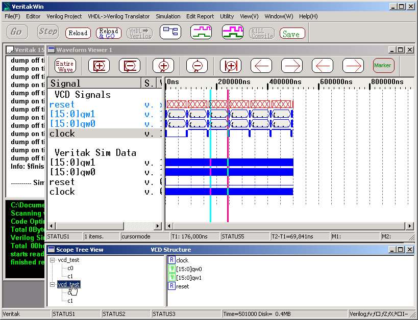
Note "VCD Structure" is displayed on title bar when vcd
scope tree, while "MODULE::vcd_test" is displayed when veritak
scope is in..
When VCD is useful?
When Veritak is used standalone RTL Simulator, VCD is not necessary, because
Veritak has all saved structure as you know. Then when is it useful? There
are 3 reasons.
- Exchange the data with other simulators.
- Post Layout Gate Simulation
- Veritak saves all data which is very convenient in RTL simulation, however
in contrary it is too big to save all the data. in post layout gate
simulation. It is recommended you use VCD only
top hierarchy or selected data to be saved if save is necessary.
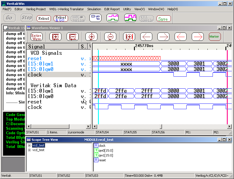
Above example shows how to enable/disable the save under
source control.. When disabled, you see xxx as data,that
is mechanism how to reduce amount of unwanted data.. (See figure below)
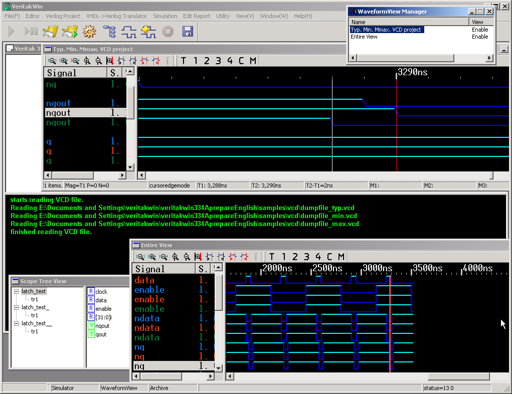
- Standalone VCD Viewer
See Fig. below.
qw1,qw0 are the same data between VCD and Veritak.
Why different ? ( VCD signals becomes xx at some interval in WaveformView)
That's why we can reduce amount of unwanted data in VCD.
2.4.1.2 VCD Project
Load the project /samples/vcd/vcd_only.vtakprj as an example.
Press
Re-Compile button if vcd file has changed.
<How to make vcd project>
It is almost the same as usual verilog files as below.
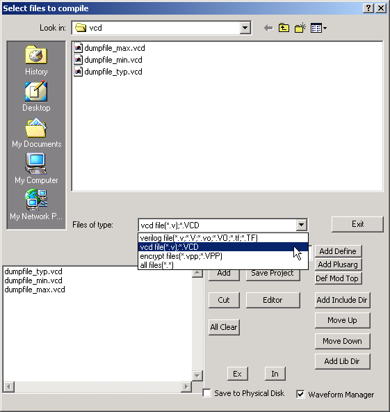
Note
- Use UseDisk option for large VCD files
- Up to 3 VCD files can be handled in a project.
- Save/Restore function is not supported regarding VCD project.
- Timescale of all vcd files should be the same
- 7times disk space will be required for sum of VCD files.
- It will take around 10minutes to compile 1GB VCD files